In this exercise the modeling with a beam element will be introduced. The method of modeling, meshing and a model analyzing will be shown. I am going to present, how to build a beam model with beam cross section which is not define be in the Femap software. In the exercise a frame model will be prepared. The theoretical model is presented below:

1. Model details
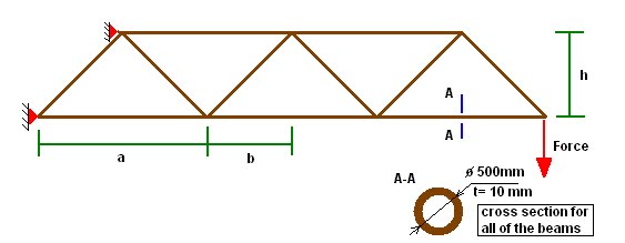
Dimensions:
A = 0.1 [m]
B = 0.03 [m]
C = 0.01 [m]
D = 1 [m]
E = 1,5 [m]
F = 0,2 [m]
Materials data:
For the model steel St36 is used.
E= 2.06e11 [N/m2]
υ= 0.3
ρ= 7.85e3 [kg/m3]
2. Geometry
To create geometry please follow the steps, most of the steps are the same as in the previous exercise so will be only decribed without a pictures:
In first step I am going to show how to prepare triangle shape:
- Creating a point:
Geometry => Point (fill in the points co ordinations in the window)
First point: 0,0,0 => OK
Second point: 0.1,0,0 => OK
Third point: 0.05,0.1,0 => OK
In the result , we receive 3 points which should be connected by the lines . The lines create a border of the surface. To create surface please follow the steps below.
Geometry => Surface=> Edge curves => (in window check 3-sides) => choose 3 edges => OK
Now do the same steps with the second profile.

I am going to prepare a first quadratic section and copy it 3 times:
Create a points:
Geometry => curve-line => points
P1: 0,0,0
P2: 0.2,0,0
P3: 1.2;0,0
P4: 1.2,1,0
P5: 0.2,1,0
Now create lines between the points:
-Coping the edges:
Geometry => Copy => Curve... => select lines from quadratic section => in repetition window insert 4 and OK=> OK
3. Properties
To create properties please follow the steps:
-Creating materials:
Please create a material like on the previous exercises.
-Creating properties
Model=>Property => select beam as a element type => shape and follow the steps below


Now please do the same with the second profile.
4. Boundary conditions
-Creating constraints:
Model=> constraints => Create/ Manage Set => follow the instruction from exercise 1
Please choose the points which are shown on the picture below.

5. Meshing
To mesh geometry follow the steps below.
Mesh=>Mesh control=>default size=> fill 0.3 in size gap
Mesh=>Mesh control => Attributes along curve => select all => follow the steps from previous exercise
Mesh => Geometry => Curve => select all => OK
To see cross section use the button shown below:

Now we have completely meshed geometry with constraints and loads. Which should looks like on the picture below: