Introduction:
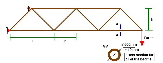
In this exercise the modeling with a beam element will be introduced. The method of modeling, meshing and a model analyzing will be shown. I am going to present, how to a whole geometry and model analyzing in the Femap software environment prepare. In the exercise a frame model will be prepared. The theoretical model is presented below:
1. Model details
Dimensions:
a= 10 [m]
b= 5 [m]
c= 5 [m]
h= 5 [m]
Materials data:
For the model steel St36 is used.
E= 2.06e-11 [N/m2]
υ= 0.3
ρ= 7.85e3 [kg/m3]
Load:
Force = 1000 N
2. Geometry
To create geometry please follow the steps, most of the steps are the same as in the previous exercise so will be only decribed without pictures:
- Creating a point:
Geometry => Point (fill in the points co ordinations in the window)
First point: 0,0,0 => OK
Second point: 10,0,0 => OK
Third point: 5,5,0 => OK
In the result , we receive 3 points which give corners of triangle.
-Creating a line:
Connect the points in the way that give a triangle shape.
Geometry => curve-line => points
-Coping the edges:
Geometry => Copy => Curve... => select all => in repetition window insert 3 and OK=> fill in like on the window => OK

In the result you have a model like on the picture below:

3. Properties
To create properties please follow the steps:
-Creating materials:
Model => Material
Please fill the STIFFNESS block as is shown on the picture below (that is minimum).

-Creating properties
Model => Property
To create beam property please follow the steps from the first exercise and pictures below.

Click Elem/Prop Type to choose the beam element.


Now the beam property is created.
4. Loads and boundary conditions
-Creating loads:
Model=> Load => Create/ Manage Set => follow the numbers from the exercise 1 or try to do yourself


-Creating constraints:
Model=> constraints => Create/ Manage Set => follow the instruction from exercise 1
Please choose the points which are shown on the picture below.


5. Meshing
To mesh geometry follow the steps below.
Mesh=>Mesh control=>default size=> fill 1 in size gap
Mesh=>Mesh control => Attributes along curve => select all => follow the steps from previous exercise
Mesh => Geometry => Curve => select all => OK
Now we have completely meshed geometry with constraints and loads. Which should looks like on the picture below:

6. Analyzing
Prepare the analysis set.

7. Results
To receive analysis results as a graphic figure follow the steps below.
F5=>Beam Diagram=> chose contour type => OK => OK

To make a stress results more clear please push F6 button and open view options.

Finally you receive the following graph:

Results with Combined Stresses

Combine stress results with deflections
Extra exercise for individual performance:
Prepare and analyze model shown on the picture below:

Brak komentarzy:
Prześlij komentarz